|
JINHUA EAST INSTRUMENT CO.,LTD
|
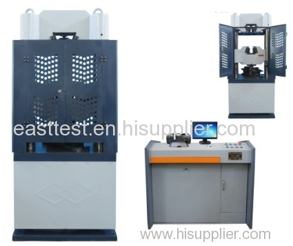
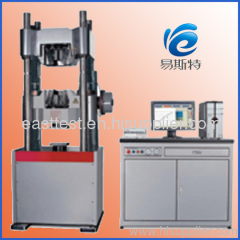
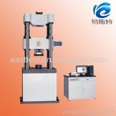
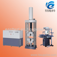
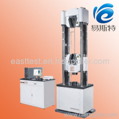
Servo universla testing machine
| Payment Terms: | T/T,L/C |
| Place of Origin: | Zhejiang, China (Mainland) |
|
|
|
| Add to My Favorites | |
| HiSupplier Escrow |
Product Detail
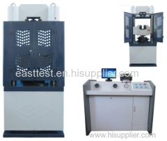
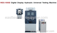
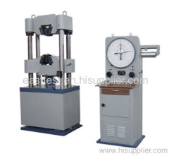
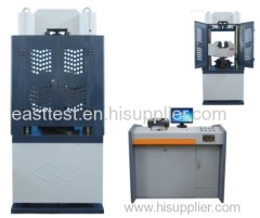
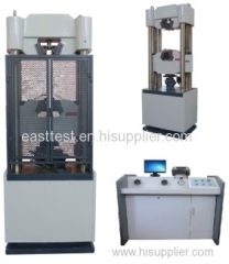
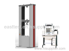
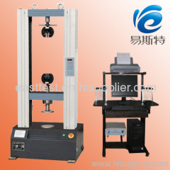
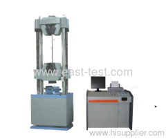
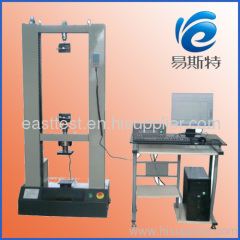
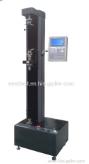
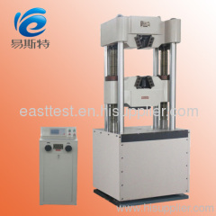
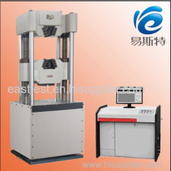
this is servo universal testing machine
WAW can implement the experimentations such as the tensile, compression, bending, cutting etc. to the metal, nonmetallic composite materials. It adopts the four vertical columns framework structure. It is of the more stable construction and the more guaranteed rigidity. It utilizes the hydraulic chuck sample automatic clamping. It employs the high precision pressureoperated sensor to measure the hyndmic force. It is of the high measuring accuracy and the wider range. It uses the high accuracy motion transducer. It adopts the high precision drawing mdchine to measure the sample deformation.It employs the high performance servo valve control.It utilizes Windows XP operation system. It can be allocated with the touch screen which is more beneficial for the operation and control of the tester.It can fulfill the multiple control modes such as the constant rate force control, constant rate stress control, constant rate deformation control, constant rate strain control,constant rate stroke control, low cycle fatigue control, consumer self-programming control etc. It can draw the multiple experimental curves such as the force-deformation, force-shift, stress-strain, force-time and so forth. It can partially amplify the experimental curve and hold the additive comparison-to the multi-curves. It can automatically seek the multiple technical parameters such as elastic module E, upper yield strength ReH, lower yield strength REL, stipulated non-proportional elongation intensity Rr, tensile strength Rm, stipulated total elongation intensity Rt, yield point percentage elongation etc. It can also print the complete experimental report and curve. It comprehensively conform with GB/T228-2002 and ISO. ASTM requirements.
Model & specification | WAW-100B | WAW-300B | WAW-600B | WAW-1000B |
Max. test force (kN) | 100 | 300 | 600 | 1000 |
Measuring range (kN) | 2%-100%FS Can improve range to 0.4%-100% FS | |||
Relative error toforce value (%) | ≤±1 | ≤±1 | ≤±1 | ≤±1 |
Distance between compression surfaces (mm) | 0-540 | 0-540 | 0-680 | 0-610 |
Max. distance between tensile jaws (mm) | 0-590 | 0-590 | 0-630 | 0-650 |
Bending test pressed rolling distance (mm) | 100-500 | 100-500 | 100-500 | 60-700 |
Clip diameter of round sample (mm) | Φ6-Φ20 | Φ10-Φ32 | Φ13-Φ40 | Φ20-Φ60 |
Clip thickness of flat sample (mm) | 0-15 | 0-15 | 0-30 | 0-40 |
Width of flat plate specimen (mm) | ≤60 | ≤60 | ≤70 | ≤80 |
Size of shearing specimen (mm) | 0-Φ10 | 0-Φ10 | 0-Φ20 | 0-Φ30 |
Effective distance | 500 | 500 | 580 | 580 |
Piston stroke (mm) | 150 | 150 | 180 | 180 |
Motor power (kW) | 1.2 | 1.5 | 2.1 | 2.1 |
Main frame outline | 805×520×1850 | 805×520×1850 | 950×630×2120 | 960×630×2220 |
Oil source control cabinet outline dimension (mm) | 580×480×1000 | 580×480×1000 | 580×480×1000 | 580×480×1000 |
Weight (about) (kg) | 1500 | 1800 | 2500 | 3000 |

